Linkage (mechanical)
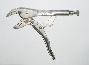
A mechanical linkage is a series of rigid links connected with joints to form a closed chain, or a series of closed chains. Each link has two or more joints, and the joints have various degrees of freedom to allow motion between the links. A linkage is called a mechanism if two or more links are movable with respect to a fixed link. Mechanical linkages are usually designed to take an input and produce a different output, altering the motion, velocity, acceleration, and applying mechanical advantage.
A linkage designed to be stationary is called a structure.
History
Mechanical linkages are a fundamental part of machine design, and yet many simple linkages were not well understood nor invented until the 19th century. Consider a stick: it has six degrees of freedom, three of which are the coordinates of its centre in space, the other three describing its rotation. Once nudged between a boulder and fulcrum it is constrained to a particular motion, to act as a lever to move the boulder. When more links are added and joined in various ways their collective motion can be further defined. Very complicated and precise motions can be designed into a linkage with only a few parts.
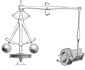
The Industrial Revolution was the golden age of mechanical linkages. Mathematical, engineering and manufacturing advances provided both the need and the ability to create new mechanisms. Many simple mechanisms that seem obvious today required some of the greatest minds of the era to create. Leonhard Euler was one of the first mathematicians to study linkage synthesis, and James Watt worked very hard to invent the Watt linkage to support his steam engine's piston. Chebyshev worked on mechanical linkage design for over thirty years, which led to his work on polynomials2. New linkage inventions, designed by need, were instrumental in cloth making, power conversion and speed regulation. Even the ability of a mechanism to produce accurate linear motion, without a reference guide way, took years to solve.
Scientists, mostly German, Russian and English, have researched this domain over the last 200 years, so that today most traditional analysis or synthesis problems (e.g. planar movement) have been solved (see online libraries under External links). Recently, compliant structures have come to the fore.
Electronic technology has replaced many linkage applications taken for granted today, such as mechanical computation, typewriting and machining. However, modern linkage design continues to advance, and designs that used to occupy an engineer for days are now optimized with a computer in seconds.
Even though servomechanisms with digital control are common, and at first glance easy to use, some motion problems (especially for quick and accurate movements) are still only soluble using linkages and cams.
Theory
The most common linkages have one degree of freedom, meaning that there is one input motion that produces one output motion. Most linkages are also planar, meaning all the motion takes place in one plane. Spatial linkages (non-planar) are more difficult to design and therefore not as common.
Kutzbach-Gruebler's equation is used to calculate the degrees of freedom of linkages. The number of degrees of freedom of a linkage is also called its mobility.
A simplified version of the Kutzbach-Gruebler's equation for planar linkages :
- <math>m = 3(n-1)-2j \, </math>
- <math>m \, </math>= mobility = degrees of freedom
- <math>n \, </math>= number of links (including a single ground link)
- <math>j \, </math>= number of one-degree-of-freedom kinematic pairs (pin or slider joints)
A more general form of the Kutzbach-Gruebler equation for planar linkages involving more complex joints:
- <math>m = 3(n-j-1)+ \sum_{n=1}^j\ f_i, </math>
Or, for spatial linkages (linkages involving 3D motion):
- <math>m = 6(n-j-1)+ \sum_{n=1}^j\ f_i, </math>
- <math>m \, </math>= mobility (degrees of freedom)
- <math>n \, </math>= number of links (including a single ground link)
- <math>j \, </math>= number of total joints, regardless of connectivity or degree-of-freedom
- <math>\sum_{n=1}^j\ f_i</math>= sum of each joint's individual degree of freedom
The mobility of hydraulic machinery can easily be identified by counting the number of independently controlled hydraulic cylinders.
Types of common joints:
- Revolute or pin, one DOF rotation. Examples are; bushings, bearings, bolted joints, rivets and hinges.
- Prismatic or slider, one or two DOF linear motion. Examples are; linear bearings, hydraulic cylinders, rollers and pistons.
- Spherical or ball and socket, three DOF rotation, usually restricted to one DOF by other joints in the mechanism.
Designers will synthesize a linkage by starting with the required output motion, mechanical advantage, velocity and acceleration. A type of linkage is chosen and modified to deliver the required performance.
Each link is treated as a vector and the vectors can be combined into a system of equations because they form a loop. The matrix is solved to create a closed form equation that relates input motion to output motion. The same is done for mechanical advantage, or any other important quantity. The equations of motion are differentiated with respect to time to find velocity and acceleration of the mechanism parts.
Types of linkages
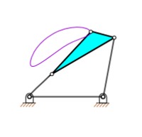
Four bar linkages are the simplest closed loop kinematic linkage. They perform a wide variety of motions with a few simple parts. They were also popular in the past due to the ease of calculations, prior to computers, compared to more complicated mechanisms.
Other notable types of linkages;
- Pantograph (four-bar, two DOF)
- Crank-slider, (four-bar, one DOF)
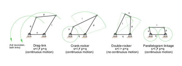
- Grashof, (four-bar, one DOF) At least one link can rotate 360°
- Five bar linkages often have meshing gears for two of the links, creating a one DOF linkage. They can provide greater power transmission with more design flexibility than four bar linkages.
- Six bar, single DOF linkages offer greater design flexibility than four bar linkages, but require more parts and are more difficult to design:3
- Watt kinematic chain
- Watt I, II
- Stephenson kinematic chain
- Stephenson I, II, III
- Parallel and Straight line mechanisms:
- James Watt's Parallel motion and Watt's linkage
- Peaucellier-Lipkin linkage, the first linkage to create a straight line output from rotary input; eight-bar, one DOF.
- A Scott Russell linkage, which converts linear motion, to (almost) linear motion in a line perpendicular to the input.
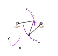
- Chebyshev linkage, which provides nearly strait motion of a point with a four-bar linkage.
- Hoekens linkage, which provides nearly strait motion of a point with a four-bar linkage.
- Sarrus linkage, which provides motion of one surface in a direction normal to another.
Uses
Linkages are primarily used as machine components and tools. Typical examples are automotive suspensions and bolt cutters. The internal combustion engine's piston/rod/crank is a classic four-bar linkage with one degree of freedom. Linkages are often the simplest, least expensive and most efficient mechanism to perform complicated motions.
One highly visible application is the windshield wiper: a four bar linkage changes the motor's rotary motion to oscillation. Some wipers also have a second set of four bar linkages to keep the wiper blades oriented correctly as they sweep. Another visible application is heavy equipment which makes extensive use of four and six bar linkages.
Spatial linkages are becoming more common due to computer aided design.
"The 4-Bar Linkage" is an adapted mechanical linkage used on bicycles. With a normal full-suspension bike the back wheel moves in a very tight arc shape. This means that more power is lost when going uphill. With a bike fitted with a 4-Bar Linkage, the wheel moves in such a large arc that it is moving almost vertically. This way the power loss is reduced by up to 30%.
See also
- Engineering mechanics
- Cam
- Kinematic pairs
- Overconstrained mechanism
- Machine
- Three-point hitch
- Lever
- Parallel motion
External links
- How round is your circle? Contains a chapters on Watt's and other linkages.
- An (at present mainly German) online library about linkages and cams is available through Digital Mechanism and Gear Library (DMG-Lib) (in German: Digitale Mechanismen- und Getriebebibliothek)
- With KMODDL there is also an English online library (contains foreign literature too)
- Linkage calculations
- Java animated linkages
- Gif animated linkages
- Introductory Linkage Lecture, 2MB PDF
- Virtual Mechanisms Animated by Java
- SAM User-friendly software for design, motion/force analysis & optimization of planar linkage, gear and belt mechanisms
| Piston engine configurations | |
|---|---|
| Straight | Single, 2, 3, 4, 5, 6, 8, 9, 10, 12, 14 |
| V | 2, 4, 5, 6, 8, 10, 12, 16, 20, 24 |
| Flat | 2, 4, 6, 8, 10, 12, 16, H |
| W | 8, 9, 12, 16, 18 |
| Other inline | H, VR, Opposed, U (Square), X |
| Other | Hemi, Radial, Rotary, Pistonless, Deltic, (Wankel) |
| Heat engines | |
|---|---|
| Stroke cycles One • Two • Four • Six • | |
| Engine types Gas turbine • Piston • Jet • Rocket engine • Steam engine • Stirling engine • Tschudi• Twingle Rotary • Wankel • Free-piston • Britalus • Coomber • Swing-piston • Orbital • Quasiturbine | |
| Valves Cylinder head porting • D slide • Four-stroke • Manifold • Multi • Piston • Poppet • Sleeve | |
| Piston layouts Single cylinder • Straight • Opposed • Flat • V • W • H • Deltic • Radial • Rocket engine nozzle • Rotary • Stelzer • Controlled Combustion • Bourke | |
| Motion mechanisms Cam • Connecting rod • Coomber rotary • Crank • Crank substitute • Crankshaft • Linkages (Evans • Peaucellier-Lipkin • Sector straight-line • Watt) • Double acting/differential cylinder | |
| Thermodynamic cycle |

